Description
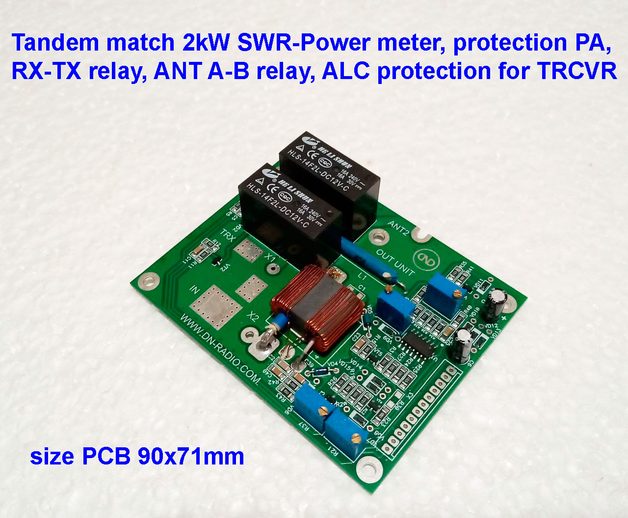
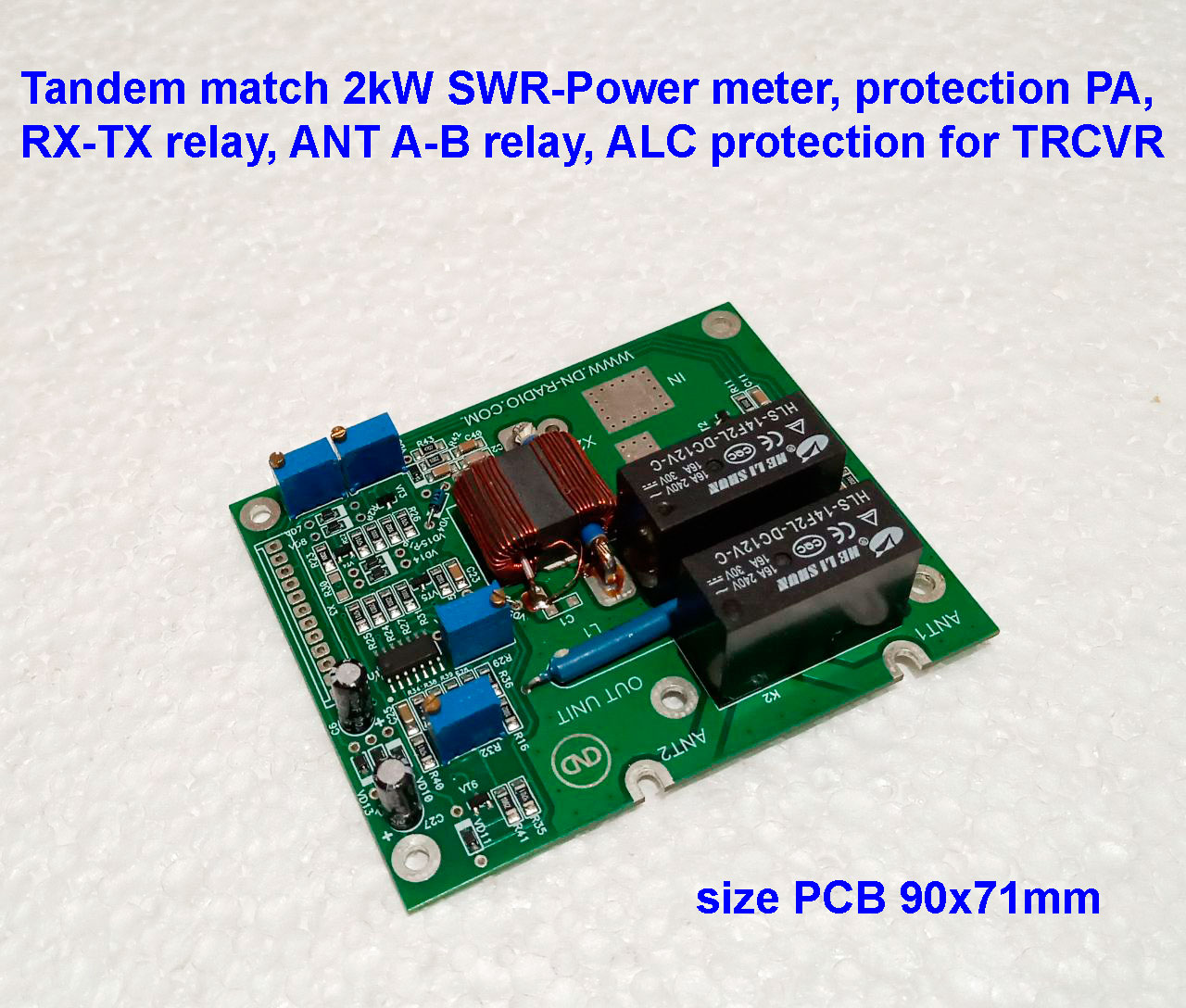
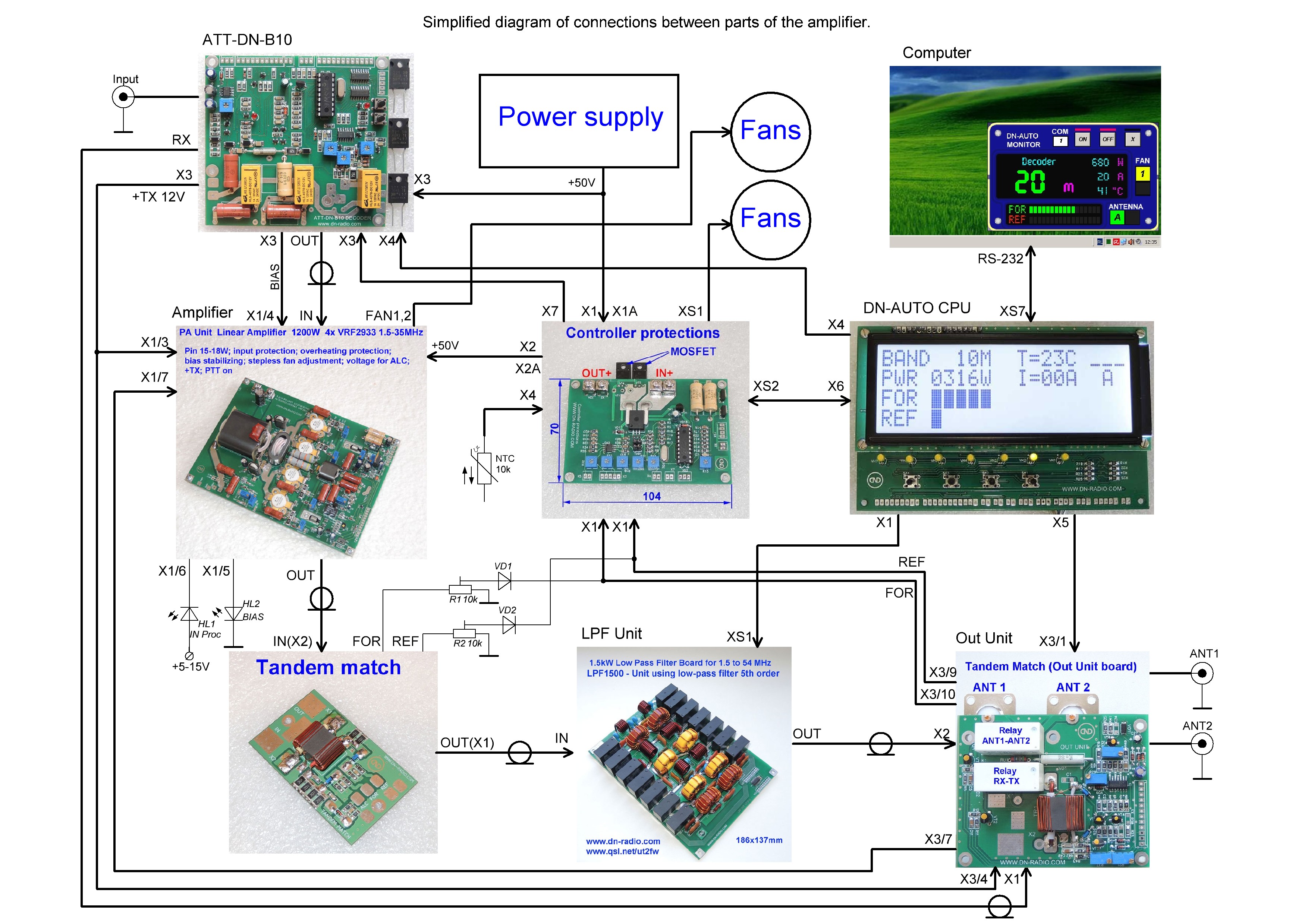
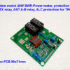
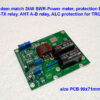
Board OUT UNIT designed for high power amplifiers (up to 2kW) in HF band 1-50MHz. This can be very useful as the core of a power meter, or as a component in an amplifier system.
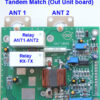
Applies a variant of the well-published “Tandem Match”, it can measure forward and reflected power at the same time, without having to throw a switch to do it.
It provides the ability to measure forward and reflected power levels; this is especially important in detecting high reflected power conditions, such as a damaged antenna, or when we forget to connect the coax to the output of an amplifier, etc.
The signal of FOR (see scheme – VD4 – U1:3) is used for measurement of power.
The signal of REF (see scheme – VD5 – U1:2) is used for measurement and for system of protection against high REF value.
Components U1:4, VT3, VT5, VT6 create “G_STOP”, “+ _ STOP” signals for protection of the amplifier. Keys of signals of protection of G_STOP and + _ STOP with “latch” (VT4). I.e. signals G_STOP, +_STOP disappear only with the return of the amplifier in the RX mode.
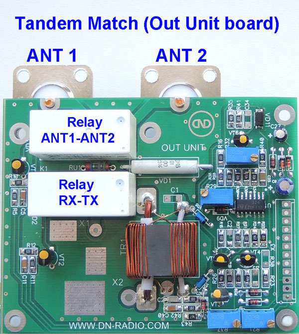
Board OUT Unit includes:
1. Directional coupler TR1,
2. Amplifiers U1:2, U1:3 for SWR-POWER meter,
3. Protection – comparator U1:4,
4. Keys switching – VT3, VT4, VT5, VT6,
5. Relays RX-TX; ANT A – ANT B – K1, K2. VT1, VT2 control the operation of the relays,
6. U1:1, VD10, VD12 form a voltage of negative polarity to ALC protect the transceiver,
7. VD6, R37 – ALC voltage to the transceiver (the voltage of the negative polarity),
8. VD1, RU1 – protection of static voltage from the antenna.
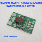
The size of the core TR1 10x20x15mm allows you to measure the power of at least 2000W.
At the same time resistance of loading has to be 50 Ohms.
To manage protections of amplifier OUT Unit gives several options signals:
G_STOP – Open drain up to 100mA, U<25V
+_STOP – output +12V up to 100mA
ALC – output to -10V
If SWR exceeds value (which you will choose as resistors R21, R29) – VT3 will open.
VT3 will stay open through VT4, while there is a voltage of +12V_TX.
When switching to RX mode – protect turns off.
A-B – switching the antenna A – antenna B. To switch to apply a voltage of +5-12V.
+12V_TX – Voltage +12V TX from the amplifier, which switches the amplifier from RX-mode to TX mode.
FOR – measurement of power
REF – measurement of SWR
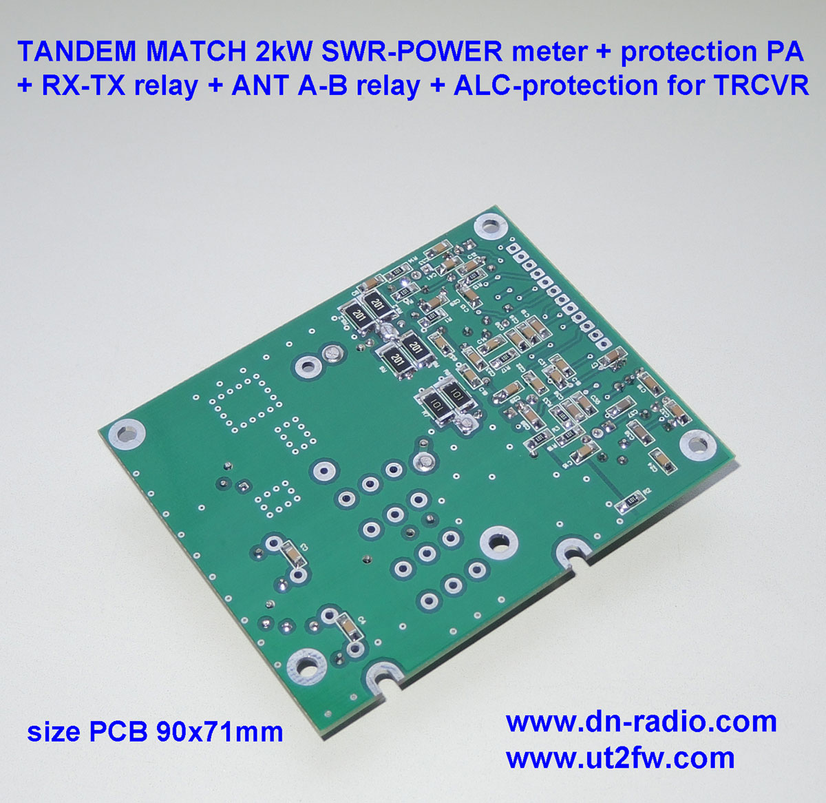
Size PCB 90x71mm
The graph shows the dependence of the output voltage on the transmitted power.
You can build a similar chart yourself online-link to the resource – https://www.kontrolnaya-rabota.ru/s/grafik/tochka/
Enter the table –
0;0
0.82;10
1.35;20
1.80;30
2.12;40
2.42;50
2.69;60
2.96;70
3.24;80
3.43;90
3.56;100