-
View the full image

-
View the full image

-
View the full image

-
View the full image

-
View the full image

-
View the full image

-
View the full image

-
View the full image

-
View the full image

-
View the full image

-
View the full image

-
View the full image

-
View the full image

-
View the full image

-
View the full image

-
View the full image

-
View the full image

-
View the full image

-
View the full image

-
View the full image

-
View the full image


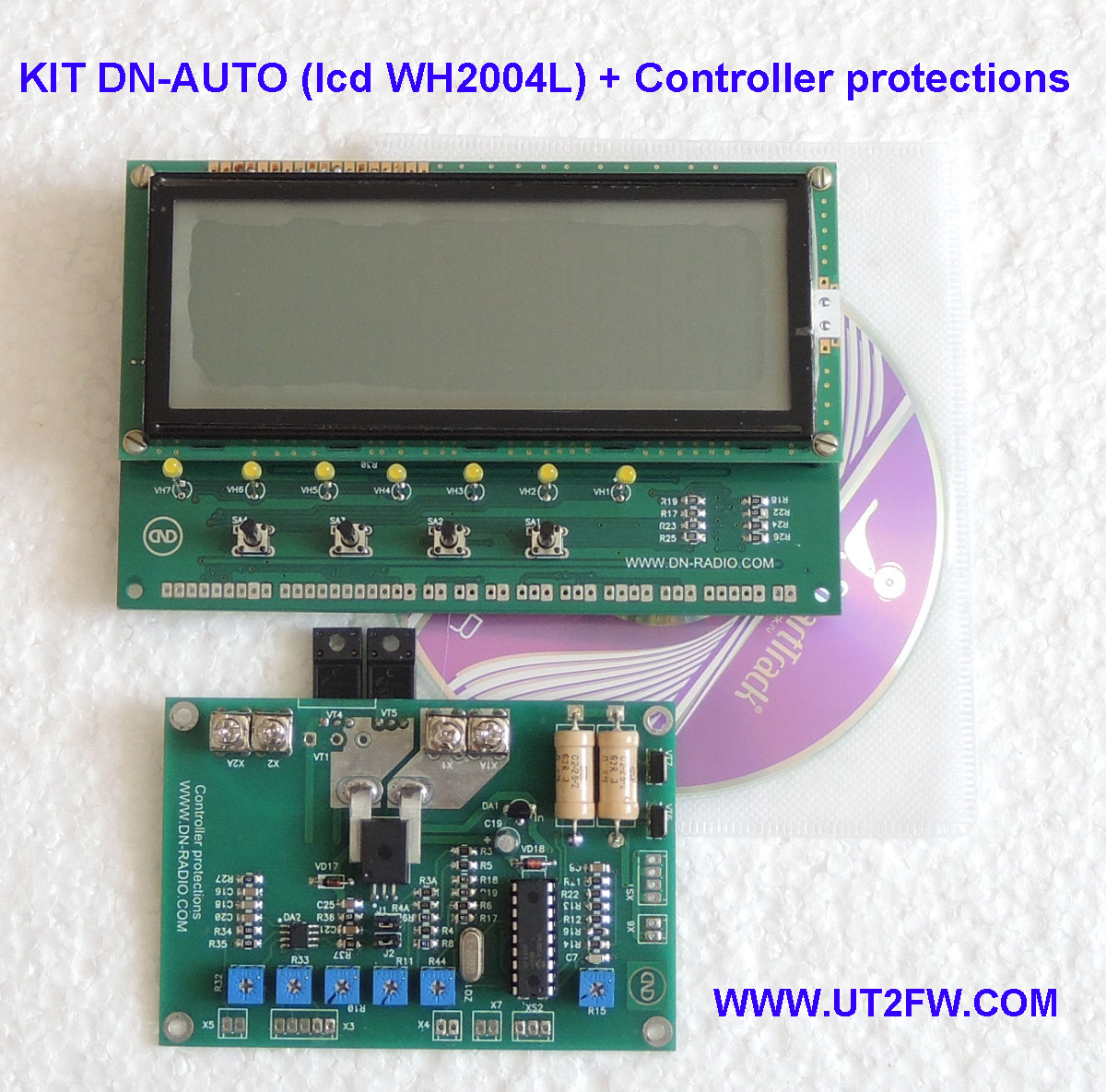
Description:
You receive a set of two boards - DN-AUTO (LCD WH2004L) + Controller Protections + CD - the second photo in the list above.
Universal Band Decoder DN-AUTO to control of the amplifier protection
The device DN-AUTO performs management functions of the Solid State amplifier.
DN-AUTO includes:
The DN-AUTO CPU board (can run independently) –
1. The Band Decoder for 10 bands (10 decoded bands from 160m to 6m including WARC).
It can get the controlling from: Kenwood (RS-232), YAESU (4-bit code), ICOM (CI-V or voltage output TRSVR) and universal decoder ATT-DN-B10.
2. Connection with computer via RS-232.
3. The control output of 10 bands.
4. The control output of 7 bands. Combined 30-20m, 17-15m and 12-10m.
5. Control ANT-A <> ANT-B (switching of two connectors for antennas).
6. Graphic information output on the LCD WH2004L or WH2004A.
The Controller Protections board –
1. Power measurement.
2. SWR measurement.
3. The current measurement. Measurement of current.
4. Temperature measurement.
5. Control of the fans working mode.
6. Switch on the MOSFET switches off the power supply voltage of the amplifier.
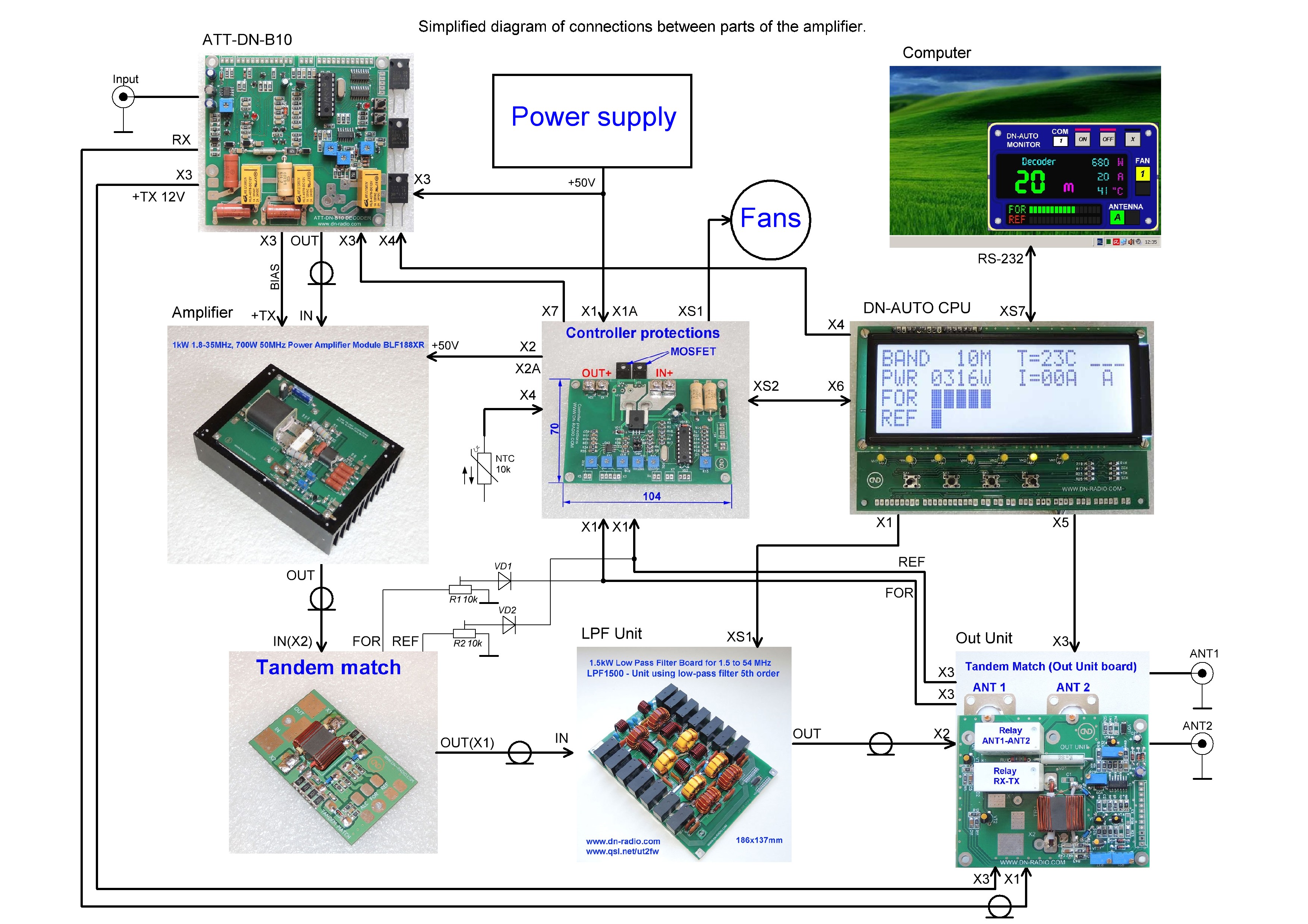
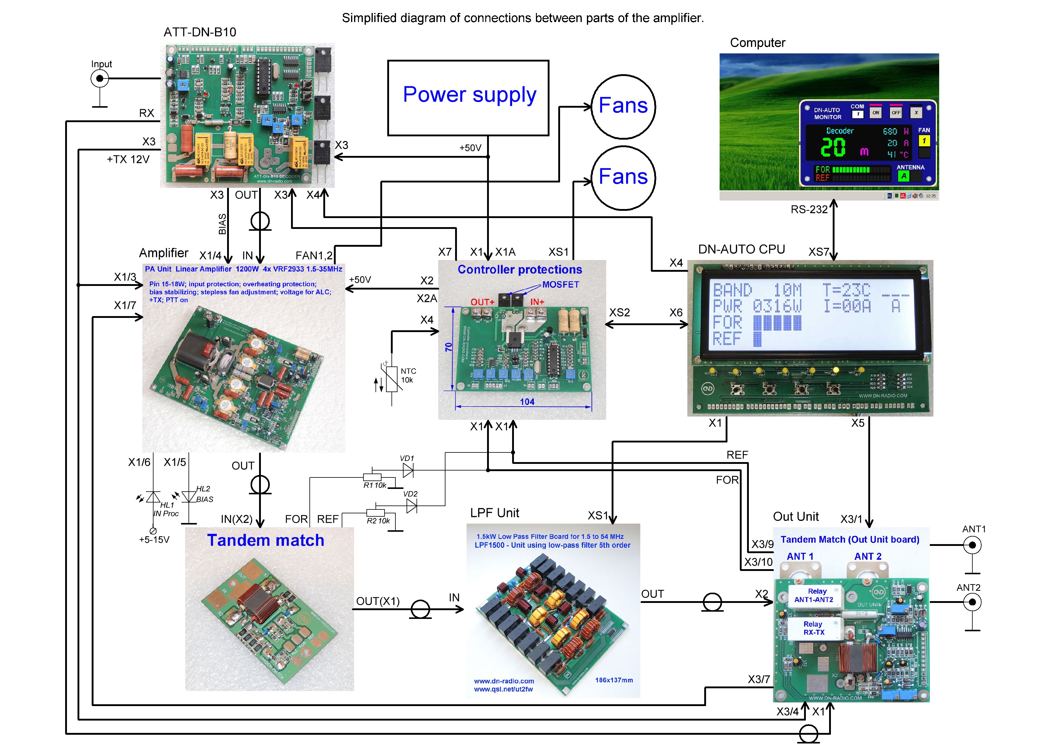
Control circuit of the amplifier
Figure 1 shows the interaction between the parts of the complex.
Information about the engaged band comes to the DN-AUTO CPU from the transceiver or computer. The microprocessor unit the DN-AUTO CPU processes the incoming information and turns on the band in the LPF Unit of the amplifier.
Additionally, the microprocessor can switch the two connectors for the antenna.
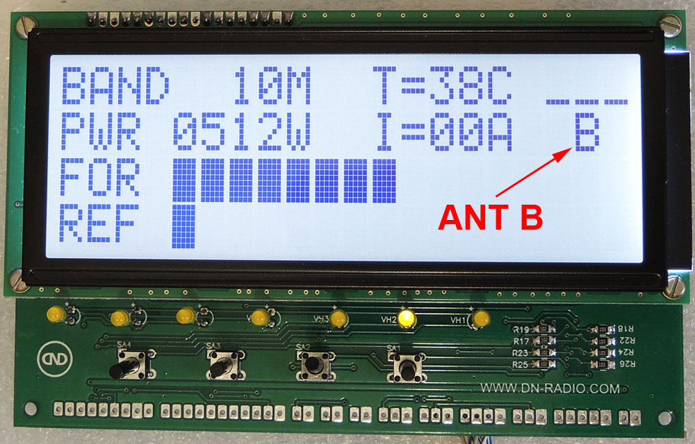
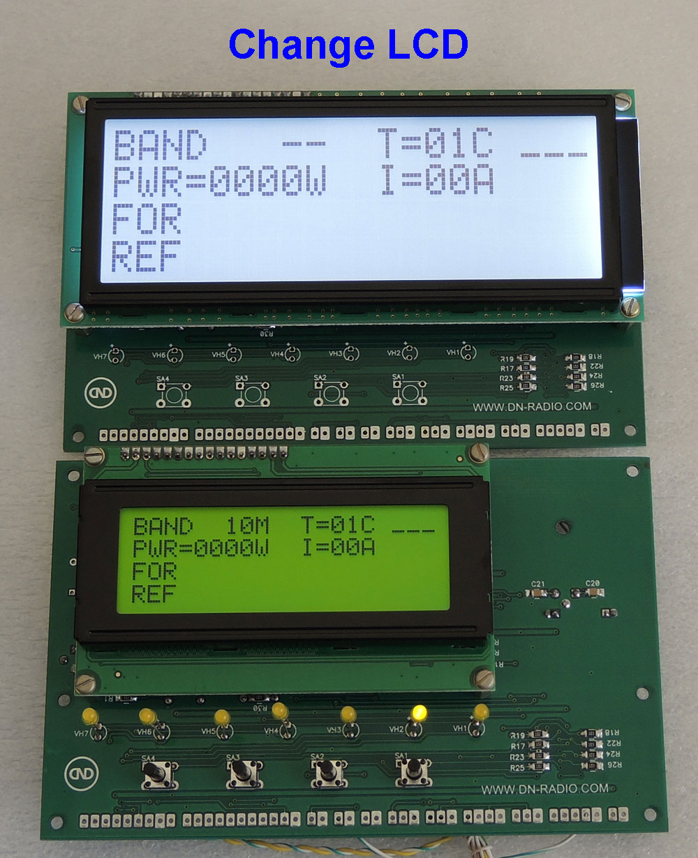
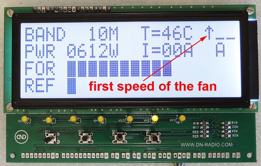
The LCD indicator displays following information: turned on band, power (in W), power FOR-REF (graphical displaying by the string), current, temperature, fan speed, antenna A-B.

Figure 1
The second board - Controller Protections - contains: measurers of current, SWR and temperature, and also the protections. Own microprocessor with high performance controls the operation of this board. This solution (the use of separate microprocessors) allowed providing the maximum performance protection of the amplifier.
If any measured parameter (SWR, current, temperature) exceeds the predetermined value, the switch on the power MOSFET turns off the power supply voltage of the amplifier.
At startup of the device the microprocessor of the Controller Protections board reads the values of the SWR, current, temperature of the microprocessor DN-AUTO CPU.
A block diagram of the DN-AUTO CPU is shown on Figure 2.
Figure 2
DN-AUTO CPU can obtain information about the band of ATT-DN-B10, PC, Kenwood, ICOM, and YAESU. The choice takes place in the menu DN-AUTO CPU.
Simultaneously DN-AUTO CPU takes the information from the ATT-DN-B10 and one type of transceiver. If you use the transceiver (transceiver selected in the menu) and the board ATT-DN-B10 is connected, then DN-AUTO CPU verifies information about the band of both RIGs. In case of discrepancy bands ATT-DN-B10 and the transceiver, the DN-AUTO CPU will go into an emergency mode. The function of additional verification increases the reliability of the entire complex of amplifier control.
The connection to COM port of computer is implemented via a connector X7 of DN-AUTO CPU. PC is used for calibration of theController Protections board. Two programs developed for the PC that allow you to test the entire complex. One program allows you to switch the bands in the DN-AUTO CPU.
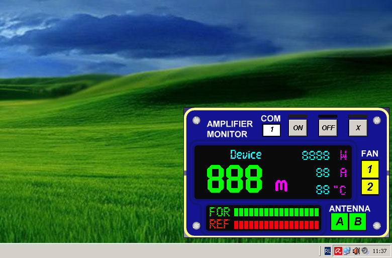
To monitoring the amplifier on the monitor of the computer, is developed program AmpMonitor.
You can put in any convenient place AmpMonitor on monitor - and control operation of the amplifier remotely.
For more information you can get on author websites links => DN-RADIO.COM and UT2FW.COM
Description of working of DN-AUTO CPU
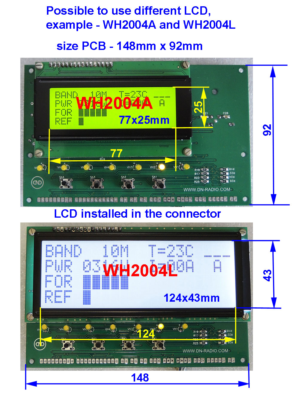
Board size is 148 x 92mm.
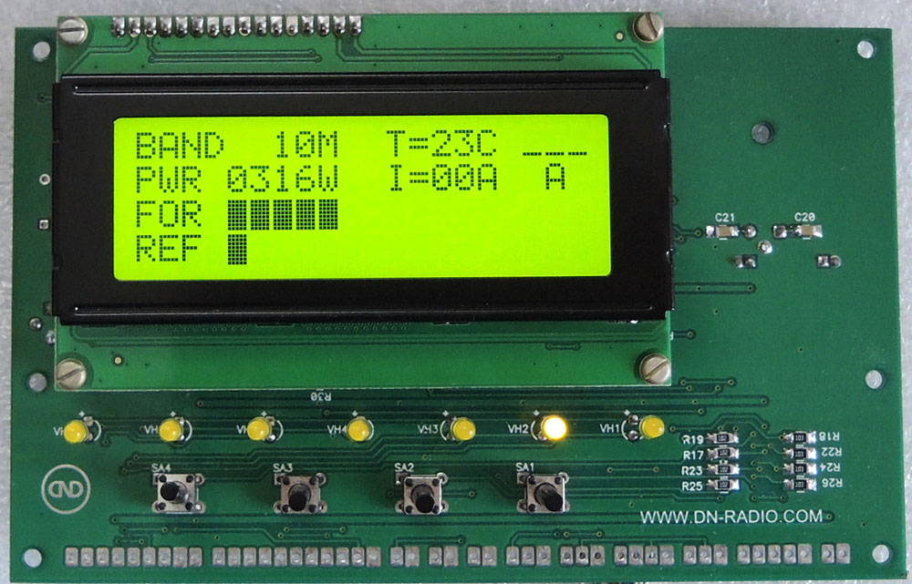
LCD WH2004L LCD WH2004A
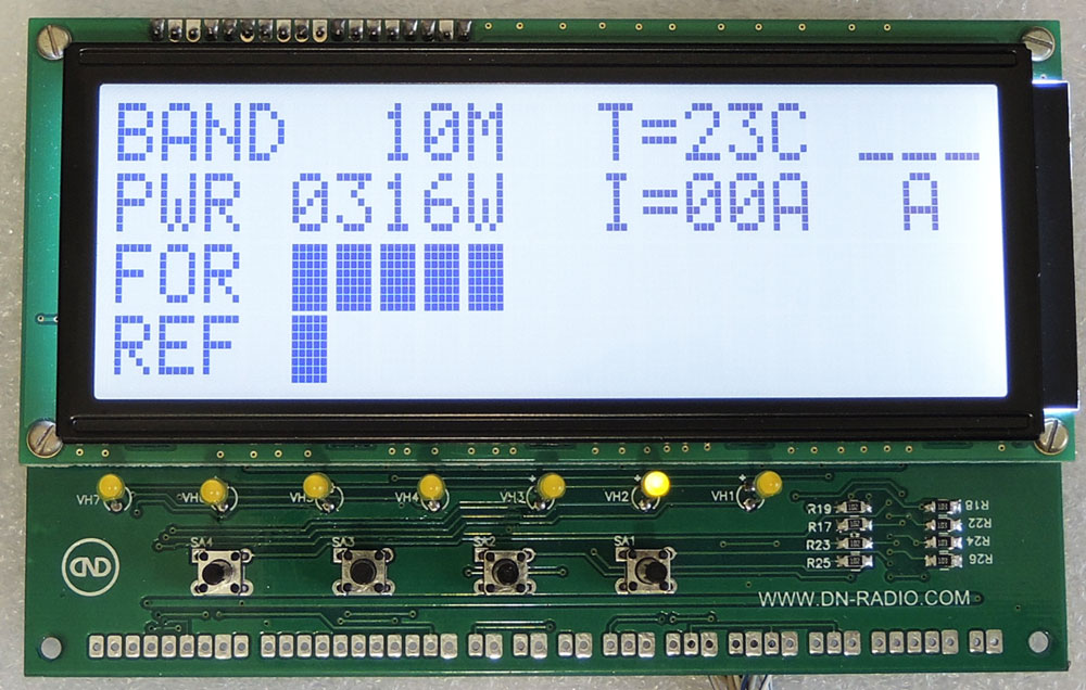
Description of the LCD DN-AUTO CPU
BAND – is a band
PWR – is a power of the amplifier
FOR – is a "forward" power
REF – is a "reflected" power
T – is a temperature
I – is a current consumed by the amplifier
A – is an antenna (there are two possible values A-В)
The power supply voltage can be between 8-15V. The optimum operating voltage is 10-12V. Current consumption is 250mA at 12V with WH2004L.
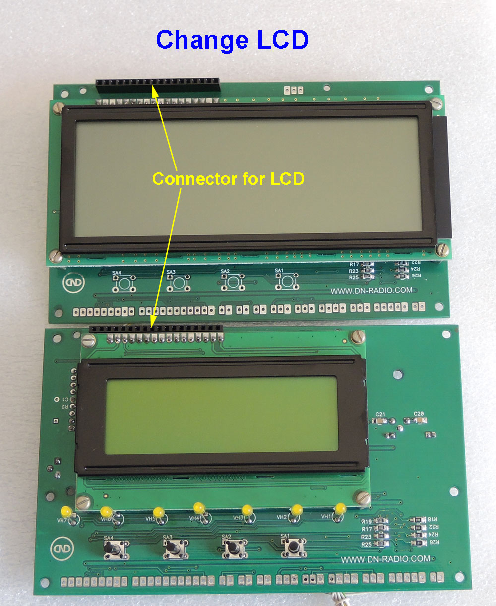
It is possible to use LCD WH2004L, WH2004A and the like. You can refuse the connector for the LCD to reduce the thickness.
The resistor (trimmer) R7 makes the LCD contrast adjustment.
Four buttons control modes:
SA1 – increase values
SA2 – decrease values
SA3 – selection of "forward" menu
SA4 – selection of "back" menu
Additional LEDs installed for indication of bands.
LEDs improve the perception of the turned on band in the case where the amplifier is located remotely:
VH1 – 6m, VH2 – 12-10m, VH3 – 15-17m, VH4 – 30-20m, VH5 – 40m, VH6 – 80m, VH7 – 160m
The pinout of connectors.
X1 Pinout
|
PIN |
SIGNAL |
DESCRIPTION |
|
1 |
160m |
Open collector Darlington transistor ULN2003. Current up to 500mA, voltage up to 50V |
|
2 |
80m |
Open collector Darlington transistor ULN2003. Current up to 500mA, voltage up to 50V |
|
3 |
40m |
Open collector Darlington transistor ULN2003. Current up to 500mA, voltage up to 50V |
|
4 |
30-20m |
Open collector Darlington transistor ULN2003. Current up to 500mA, voltage up to 50V |
|
5 |
17-15m |
Open collector Darlington transistor ULN2003. Current up to 500mA, voltage up to 50V |
|
6 |
12-10m |
Open collector Darlington transistor ULN2003. Current up to 500mA, voltage up to 50V |
|
7 |
6m |
Open collector Darlington transistor ULN2003. Current up to 500mA, voltage up to 50V |
|
8 |
GND |
Ground |
|
9 |
+12V |
Output +12V. Connected in parallel to a contact +12V X10 |
X2 Pinout
|
PIN |
SIGNAL |
DESCRIPTION |
|
1 |
+5V |
The power supply voltage +5V for additional decoder bands. Current up to 50mA |
|
2 |
GND |
Ground |
|
3 |
OUT |
Connection of additional decoders bands |
|
4 |
GND |
Ground |
X3 Pinout
|
PIN |
SIGNAL |
DESCRIPTION |
|
1 |
160m |
Voltage +5V, current up to 10mA. Details look in the description. |
|
2 |
80m |
Voltage +5V, current up to 10mA. Details look in the description. |
|
3 |
40m |
Voltage +5V, current up to 10mA. Details look in the description. |
|
4 |
30m |
Voltage +5V, current up to 10mA. Details look in the description. |
|
5 |
20m |
Voltage +5V, current up to 10mA. Details look in the description. |
|
6 |
17m |
Voltage +5V, current up to 10mA. Details look in the description. |
|
7 |
15m |
Voltage +5V, current up to 10mA. Details look in the description. |
|
8 |
12m |
Voltage +5V, current up to 10mA. Details look in the description. |
|
9 |
10m |
Voltage +5V, current up to 10mA. Details look in the description. |
|
10 |
6m |
Voltage +5V, current up to 10mA. Details look in the description. |
|
11 |
GND |
Ground. |
X4 Pinout
|
PIN |
SIGNAL |
DESCRIPTION |
|
1 |
IN |
To the OUT board ATT-DN-B10 |
|
2 |
OUT |
To the IN board ATT-DN-B10 |
|
3 |
GND |
Ground |
X5 Pinout
|
PIN |
SIGNAL |
DESCRIPTION |
|
1 |
ANT A-B |
Voltage 0V for ANT-A. Voltage +5V, current up to 10mA for ANT-B |
|
2 |
GND |
Ground. Power supply return. Chassis ground |
X6 Pinout
|
PIN |
SIGNAL |
DESCRIPTION |
|
1 |
IN |
To the OUT pin 1 XS2 of the Controller Protections Board |
|
2 |
OUT |
To the IN pin 3 XS2 of the Controller Protections Board |
|
3 |
GND |
Ground. To the gnd pin 2 XS2 of the Controller Protections Board |
X7 Pinout
|
PIN |
SIGNAL |
DESCRIPTION |
|
1 |
OUT |
To the RxD COM port PC |
|
2 |
IN |
To the TxD COM port PC |
|
3 |
GND |
Ground |
X8 Pinout
|
PIN |
SIGNAL |
DESCRIPTION |
|
1 |
OUT |
To the RxD RS232 Kenwood |
|
2 |
IN |
To the TxD RS232 Kenwood |
|
3 |
GND |
Ground |
X9 Pinout
|
PIN |
SIGNAL |
DESCRIPTION |
|
1 |
CI-V |
To the CI-V ICOM |
|
2 |
GND |
Ground |
X10 Pinout
|
PIN |
SIGNAL |
DESCRIPTION |
|
1 |
+12V |
The power supply voltage from +12VDC to +14VDC The current consumption 250mA |
|
2 |
GND |
Ground. Power supply return. Chassis ground |
X11 Pinout
|
PIN |
SIGNAL |
DESCRIPTION |
|
1 |
Band 0 |
To the band data A YESU |
|
2 |
Band 1 |
To the band data B YESU |
|
3 |
Band 2 |
To the band data C YESU |
|
4 |
Band 3 |
To the band data D YESU |
|
5 |
GND |
Ground |
X12 Pinout
|
PIN |
SIGNAL |
DESCRIPTION |
|
1 |
0-8V |
To the connector ACC “Band” 0-8V ICOM |
|
2 |
GND |
Ground |
Connecting the DN-AUTO CPU
To connect the wires to the DN-AUTO CPU you can solder the wires into metalized holes in the board. The second variant is the connection of wires using additional connectors with a pitch between connectors of 2.54 mm. The types of possible connectors are NC25, NSR, WF, WH, SH2541, PLS...
WF type connectors are shown schematically on the figure of the board.
It is enough to apply the voltage 12V, current up to 250mA to the connector X10 to verify the health of the DN-AUTO CPU.
Without specify information about the band the BAND indications can have values of 160M or 30M in depending on the choice of device type in the SETUP BAND menu.
While connection of the various RIGs to the DN-AUTO CPU, you should consider the possibility of electromagnetic interference in long cables. Such interferences can interfere with the operation of the CPU. Therefore, use ferrite filters and shielding of extra long cables.
Kenwood transceiver has to be connected to X8.
Connector X8 is a RS232 port. Settings for Kenwood are standard – Baud Rate: 9600 [bps], Stop Bit: 1bit.
An additional jumper of contacts No. 7-8 of the transceiver COM connector is required in some models of the Kenwood.
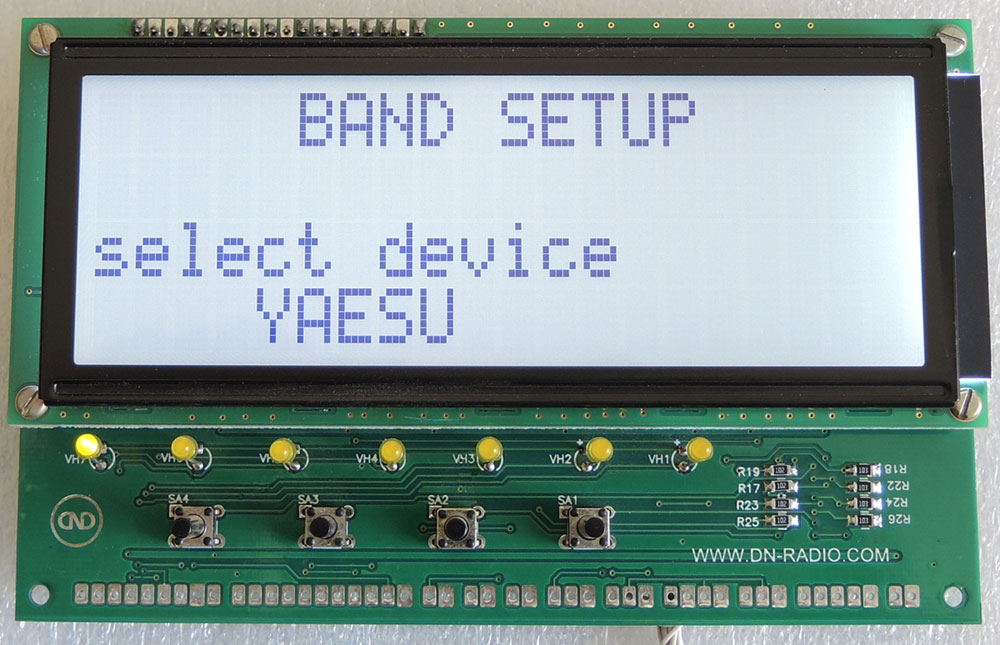
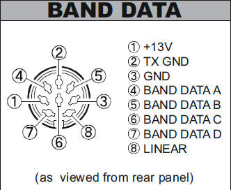
The YAESU transceiver has to be connected to X11.
The output data about the band YAESU BCD has to be connected here. The figure of the FT1000MP Band Data Connector is shown as an example –
Eponymous contacts of the FT1000MP Band Data Connector and X11 have to be connected.
These are the contacts:
pin 4 BAND DATA A – Data A Yaesu pin 1 X11
pin 5 BAND DATA B – Data B Yaesu pin 2 X11
pin 6 BAND DATA C – Data C Yaesu pin 3 X11
pin 7 BAND DATA D – Data D Yaesu pin 4 X11
pin 3 GND – gnd pin 5 X11
Transceiver ICOM can be connected in two ways.
Connection ICOM via CI-V to X9. Standard settings of the ICOM –
CI-V BAUD RATE: 9600 [bps]
CI-V ADDRESS: 70
CI-V Transceiver: ON
If there are failures in the work of the CPU DN-AUTO while a large power of the amplifier, and if additional shielding of long wires or ferrite filters do not help, you can apply the additional capacitor. Wiring diagram for the capacitor 
The capacitance of the capacitor should be picked up. The larger the capacitance of the capacitor, the better it absorbs interference. However, it more shunts the useful signal from the ICOM. Large capacity of the capacitor can block the work of the port CI-V ICOM.
Connecting of ICOM Band voltage output.
Typically, this is output of the ICOM ACC2 connector (check carefully the manual of the transceiver). Connection ICOM via Band voltage output to X12.
For example, ACC 2 IC-7600 –

pin 4 ACC 2 – ACC ICOM pin 1 X12
pin 2 ACC 2 – gnd pin 2 X12
Read the manual of the transceiver before connecting. For example, for IC-7000, you first need to activate the output Band voltage (pin 5 ACC of the socket). In the operator's manual of IC-7000 the description of the activation is presented in p. 140 –

Connection to COM port of the computer to the connector X7.
X7 is RS232. It does not have any peculiarities. It needs to be protected from high-frequency interferences of the amplifier by standard way – shielded wires, ferrite filters.
Connection of Controller Protections:
pin 1 OUT XS2 Controller Protections – pin 1 IN X6
pin 2 GND XS2 Controller Protections – pin 3 gnd X6
pin 3 IN XS2 Controller Protections – pin 2 OUT X6
Connecting of ATT-DN-B10:
pin 1 OUT X4 ATT-DN-B10 – pin 1 IN X4
pin 2 IN X4 ATT-DN-B10 – pin 2 OUT X4
pin 3 GND X4 ATT-DN-B10 – pin 3 gnd X4
Connecting additional decoders bands to X2.
In some cases, the use of additional decoder bands instead of the decoder, which is installed on board the DN-AUTO CPU, is more profitable.
For example, when a distance between DN-AUTO CPU and motherboard with switchable filters is large it is more profitable to have an additional decoder next to the filters' board. It is enough to bring just two wires – the signal wire to the screen and the wire of power supply voltage +5V to the additional decoder. Instead of using 10 long wires to switch 10 bands between of the filters' board and DN-AUTO CPU.
While using of an additional decoder, the decoder of DN-AUTO CPU board will work too.
X1 – the control of amplifier's low pass filters.
ULN2003A is used. Manufacturer of the ULN2003A says 500-mA-Rated Collector Current (Single Output) and High-Voltage Outputs: 50 V.
As shown by the experience of using ULN2003A, you should not exceed 300mA and 36V.
ULN2003A have protection diodes (Clamp Diodes Output), so no need to connect diodes parallel to the relay of filters.
X3 is the control for the 10 bands.
The maximum current for one output is 25mA. You should not exceed 15mA. Avoid static electricity. Not designed to switch a relay. You should use an additional driver of loads for 10 channels, for example, 2pcs ULN2003 to control a relay.
X5 is used for switching two antennas or different RIGs.
The maximum current is 25mA. You should not exceed 15mA. Avoid static electricity. Not designed to switch a relay. You should use an additional driver of loads, for example, a key on the transistor to control a relay.
Detailed diagrams of connections are given on CD to the device. You can ask your question on the website.
Description of the menu DN-AUTO CPU
Entrance to the Menu occurs by subsequent pressing on the SA3-SA4 button.
The SA3 button causes the direct sequence of menu pages selection.
The SA4 button causes the reverse sequence of menu pages selection.
The SA1-SA2 buttons are used to modify the values of Menu settings.
When power of the DN-AUTO CPU is turned off, the settings are saved.
The LCD screen flickers in the "OVERLOAD" mode of the DN-AUTO CPU. After removal of the overload the DN-AUTO CPU will be in the "OVERLOAD" mode for another 5 seconds. In the "OVERLOAD" mode the DN-AUTO CPU sends a signal to the Controller Protections board to turns on the protection of the amplifier.
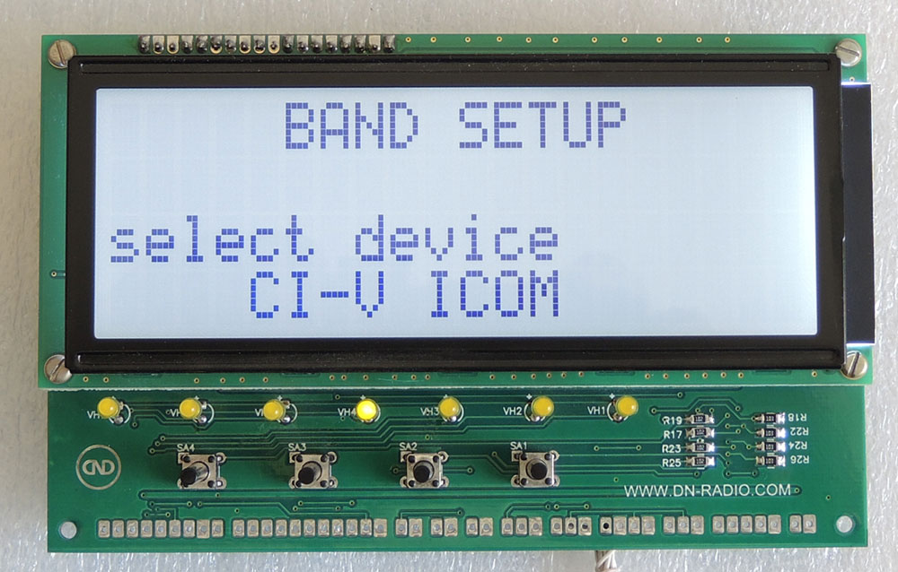
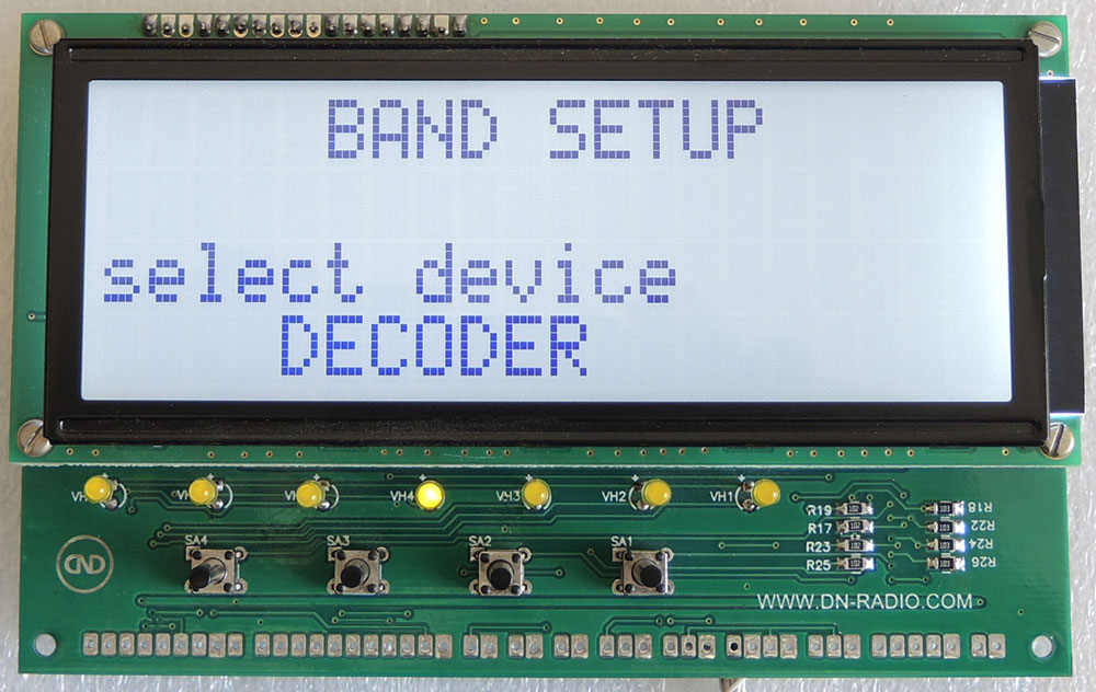
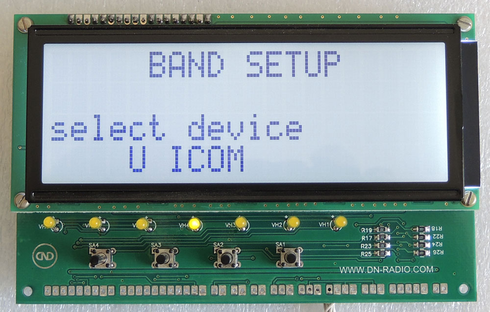
Menu BAND SETUP.
Selection of the device type about a band occur on this Menu page.
You can use SA1-SA2 buttons to select device type. It is enough to choose the desired type and exit the Menu page by clicking of the SA4 button, the type of the selected device will be saved.


Menu TEMPERATURE SETUP.
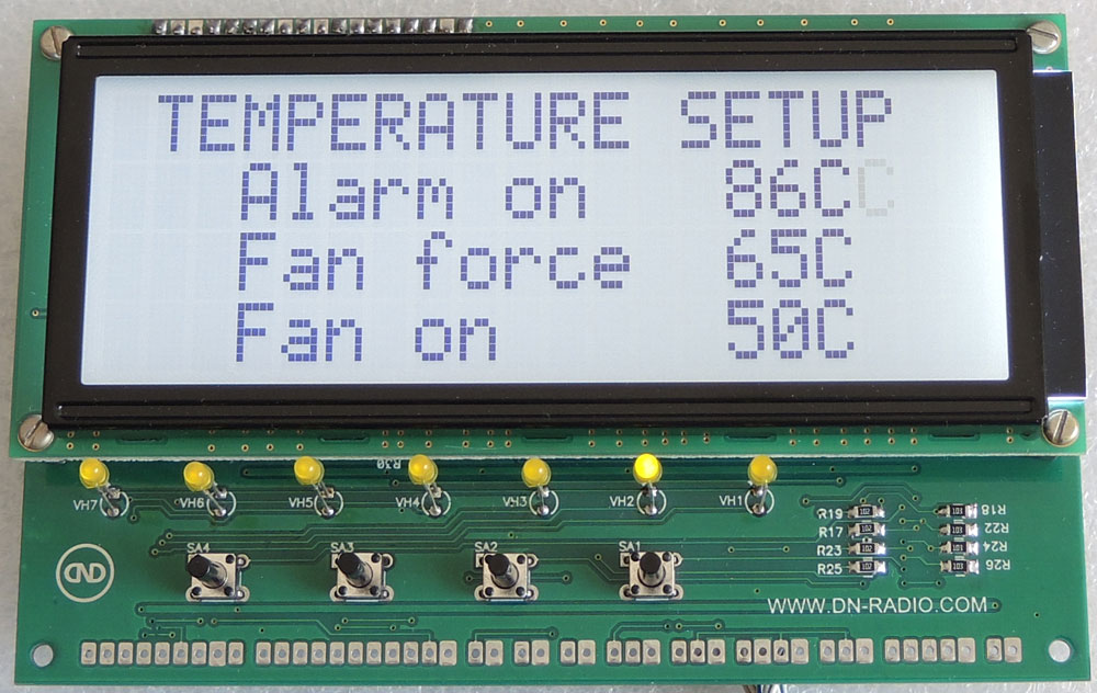

The position of the temperature that is active to change a value flickers. SA1-SA2 buttons set a temperature for each value – Alarm on, Fan force, and Fan on.
Alarm on is the limit temperature value. It depends on the location of the temperature sensor. The closer the temperature sensor is located to the transistors of the amplifier – the higher can be the maximum temperature Upon reaching the Alarm on temperature the DN-AUTO CPU goes into "OVERLOAD" mode –
The DN-AUTO CPU is in the "OVERLOAD" mode to reduce the temperature below the set value Alarm on + 5 seconds.
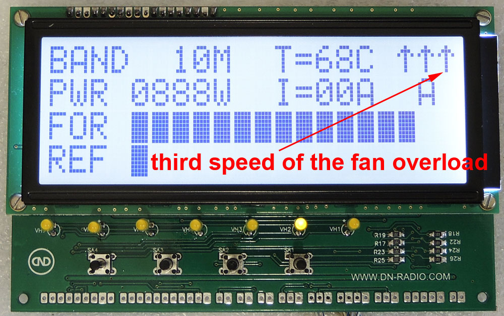
The values of temperature the Fan force and Fan on depends on various factors. It is the size of the amplifier case, size of the heatsink of transistors, and performance of the fans. Usually the fans are turned on (the values of Fan on) at a temperature of 40-50°C. The forced ventilation mode (the values of Fan force) is turned on at a temperature above of 55-65°C.
Menu CI-V ICOM.
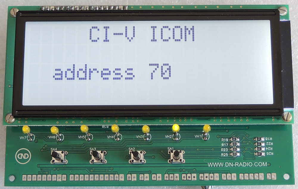
Selection of the CI-V port for ICOM. You should look the address in the description of your ICOM transceiver.
Menu SWR SETUP.

The DN-AUTO CPU can be used with amplifiers from 100W up to 2500W. You can select power depending on the maximum power of your amplifier – 100W, 500W, 1000W, 1500W, 2000W, 2500W.
Menu Imax SETUP.
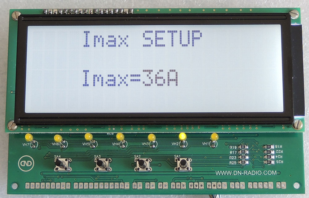
Set the maximum current consumption of your amplifier. The DN-AUTO CPU goes into the "OVERLOAD" mode at achieving the set value Imax of the current.
After reducing the current below the Imax value the DN-AUTO CPU is in "OVERLOAD" mode for another 5 seconds.
Menu SWR SETUP.
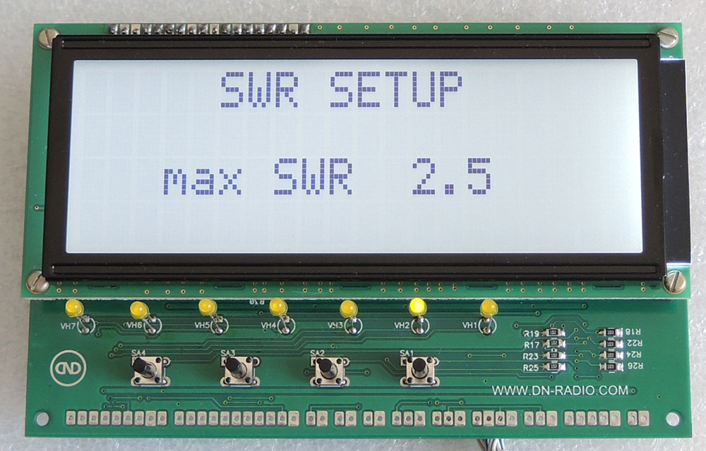
Set the maximum SWR value for your amplifier. As soon as the preset in this menu value of SWR will be reached, the DN-AUTO CPU goes into the "OVERLOAD" mode.
The DN-AUTO CPU is still in the "OVERLOAD" mode within 5 seconds after the overload SWR.
Indication of three modes of fans –

Description work of the Controller Protections
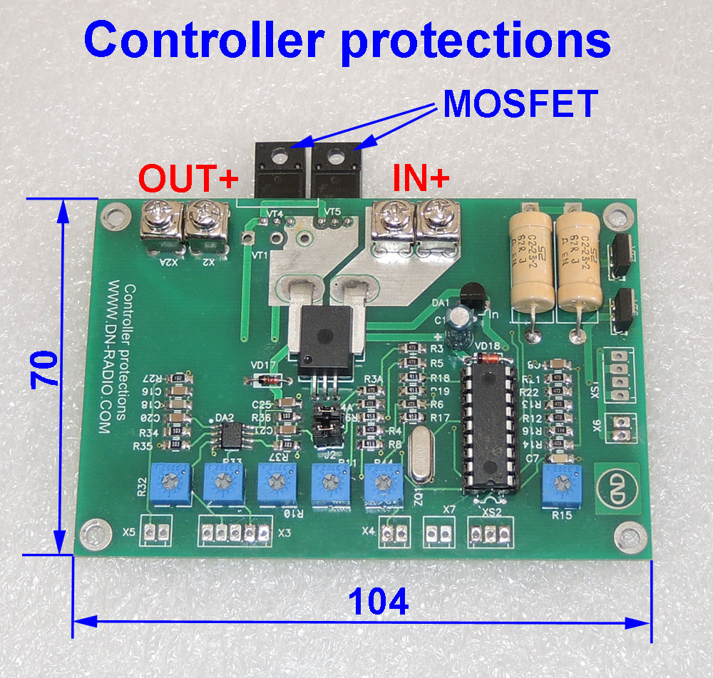
Board size is 104 x 70mm.

The power supply voltage can be between 8-15V. The optimum operating voltage is 10-12V. Current consumption is 20mA at 12V.
The device is switched on the microprocessor DD1 Controller Protections receives the data about SWR, Imax, temperatures from the DN-AUTO CPU.
The microprocessor DD1 measures:
1. The voltage (0-+5V) FOR-REF from the SWR-meter – the X3 connector (pin 2 REF, pin 4 FOR).
2. The voltage (0-+10V) from the temperature sensor (thermistor) – the X4 connector.
3. The current 0-50A from the U1 sensor.
The inputs of the SWR-meter and temperature have individual adjustments R32, R33, R44. Therefore, you can apply different types of SWR-meters and temperature meters with Controller Protections.
Amplifiers DA2:1, DA2:2 serve to further isolate of the DD1 from the high-frequency part (SWR-meter) of the amplifier. In addition to the adjustments R32, R33 for the FOR-REF from the SWR-meter, it is possible to change the gain DA2:1, DA2:2 (by the change of the resistors ratio R34-R35, R36-R37). That allows the use of Controller Protections even for amplifiers of low power.
Today there is a whole class of powerful MOSFET, which can switch large currents. A key on power MOSFET is applied in the Controller Protections to disconnect the power supply voltage of the amplifier.
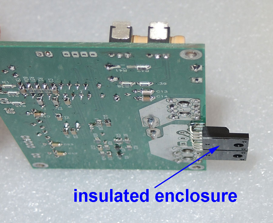
Can be used as parallel connection of two MOSFETs (VT4-VT5) in the casing TO-220 (e.g. FQP47P06) and one power MOSFET (VT1) in the casing TO-247. You can switch up to 90A, 60V in the variant of Controller Protections (with two VT4-VT5 FQPF47P06), which is shown on the photo below.
The MOSFET VT4, VT5 does not need to be isolated from the chassis. Losses through the switch are very small, so the heating of the MOSFET is minimal.
Dual contacts (X1-X1A; X2-X2A) are used to connect wires. It is sometimes easier to use two parallel wires of smaller cross section, instead of a single larger cross-section while high currents. By twos contacts are set for this.

Two separate ports are involved to enable protection of the amplifier. There are pin 12 DD1 – ALARM_I and pin 13 DD1 – ALARM_HF. Two separate ports for control of protections applied in order to do not turn off the amplifier at the slightest overload – for example, when the maximum SWR or temperature is reached. It is sufficient to reduce the amplifier power and you can continue its further use upon reaching the maximum SWR and temperature.
The port ALARM_I controls the key on MOSFET – opens it when the current is reached a value of Imax that is set in the DN-AUTO CPU Menu. Thus protecting the amplifier from exceeding the current consumption.
When exceeding the values of SWR and temperature limits (Alarm on) the port ALARM_HF works – the voltage +5V arises on pin #1 of the X7 connector. This signal should be used to turn on the protection of the amplifier. For example, to shunt the amplifier input by a resistor to turn off the BIAS.
When the maximum SWR and temperature is reached it is sufficient to interconnect ALARM_I and ALARM_HF to the key on the MOSFET shuts off the amplifier power supply voltage.
The key on MOSFET has an additional external control. It is enough to close the pins #1-2 of the X5 connector to disconnect the key.
VT6, VT7 are turn on ventilators (XS1 connector). VT7 is turned on when the temperature reaches Fan on. VT6 is turned on when the temperature reaches Fan force. Resistors R7, R40 are reduced the fan voltage thereby to reduce the airflow from the fan. Resistors R41, R42 are used for a variety of connectivity options of VT6, VT7, R7, R40 to fans. For example, when you install R42 pin 4 of the XS1 connector will control the maximum voltage of the fan when reaching the Fan on. And pin 2 of the XS1 connector will control the lowered voltage for the fan through resistors R7, R40.
Calibration of DD1 settings while resistors R10, R11, R15, perform production of Controller Protections. Therefore, the position R10, R11, R15 does not change during operation.
The pinout of connectors.
X1, X1A Pinout
|
PIN |
SIGNAL |
DESCRIPTION |
|
X1 |
+48V |
+5-55V power supply current, up to 50A INPUT |
|
X1A |
+48V |
+5-55V power supply current, up to 50A INPUT |
X2, X2A Pinout
|
PIN |
SIGNAL |
DESCRIPTION |
|
X1 |
+48V |
+5-55V power supply current, up to 50A OUTPUT |
|
X1A |
+48V |
+5-55V power supply current, up to 50A OUTPUT |
XS1 Pinout
|
PIN |
SIGNAL |
DESCRIPTION |
|
1 |
+12V |
Voltage for fan FAN2 – +5-48V |
|
2 |
FAN2 |
Open Drain (MOSFET IRLU120). Current up to 1A, voltage up to 50V |
|
3 |
+12V |
Voltage for fan FAN1 – +5-48V |
|
4 |
FAN1 |
Open Drain (MOSFET IRLU120). Current up to 1A, voltage up to 50V |
XS2 Pinout
|
PIN |
SIGNAL |
DESCRIPTION |
|
1 |
OUT |
To the IN pin 1 X6 board DN-AUTO CPU |
|
2 |
GND |
Ground. To the gnd pin 3 X6 board DN-AUTO CPU |
|
3 |
IN |
To the OUT pin 2 X6 board DN-AUTO CPU |
|
PIN |
SIGNAL |
DESCRIPTION |
|
1 |
GND |
Ground |
|
2 |
IN REF |
Input 0V – +5V from the SWR-meter |
|
3 |
GND |
Ground |
|
4 |
IN FOR |
Input 0V – +5V from the SWR-meter |
|
5 |
GND |
Ground |
X4 Pinout
|
PIN |
SIGNAL |
DESCRIPTION |
|
1 |
T+ |
Voltage 0 – +10V from the thermistor 5-10K. Apply +12V via thermistor 5-10K. |
|
2 |
GND |
Ground |
X5 Pinout
|
PIN |
SIGNAL |
DESCRIPTION |
|
1 |
SWITCH |
Connect to gnd (pin 2). Disable key MOSFET. |
|
2 |
GND |
Ground |
X6 Pinout
|
PIN |
SIGNAL |
DESCRIPTION |
|
1 |
+12V |
The power supply voltage from +12VDC to +14VDC. The current consumption 20mA. |
|
2 |
GND |
Ground. Power supply return. Chassis ground. |
X7 Pinout
|
PIN |
SIGNAL |
DESCRIPTION |
|
1 |
OUT |
Voltage +5V, current up to 10mA. For to manage the additional protections. |
|
2 |
GND |
Ground |
Detailed diagrams of connections are given on CD to the device.